Circuit Board Construction

I chose 1/8″ G-10, a flameproof rated glass epoxy material, for my circuit boards. When purchasing the G-10, I requested the boards to be cut to length (12″ for main circuit board, 4″ for filter cap board) but the main circuit board still needed to be ripped from 3-1/8″ wide to its finish width of 2-1/2″ (for more info on why, see post: New Circuit Board Layout). To rip the G-10 board lengthwise, I used an orbital jig saw and a fence to ensure that my cut was straight. The finished cut was clean and straight, but the glass epoxy G-10 board made mincemeat of my blade.

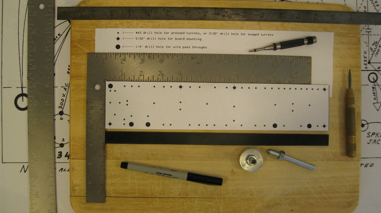
The next step was to transfer the turret and hole layout onto the G-10 board, using my redesigned circuit board layout. I used a center-punch to mark the hole locations.

Circuit Board - Transfer Layout

After using my friend’s drill-press for several other projects, I decided that it was prudent to purchase one of my own. For ease of storage and space considerations, I decided to get a 10 inch table drill-press. Within 30 minutes I had the drill-press assembled and properly adjusted. My first project using my new drill-press was to fabricate an anvil and swage out of two 5/16″ bolts. I followed the tutorial available on TubeDepot.com.

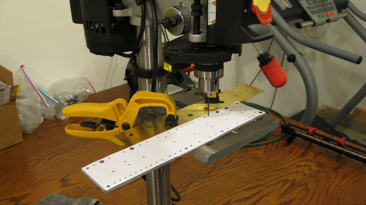
Next, it was time to drill all of the circuit board holes. I thought that it would be easier locate and align the drill if I didn’t remove the paper template; and because the paper template was securely attached to the G-10 with pieces of Scotch tape I decided to simply leave it attached during the drilling process.

Circuit Board - Drilling Holes

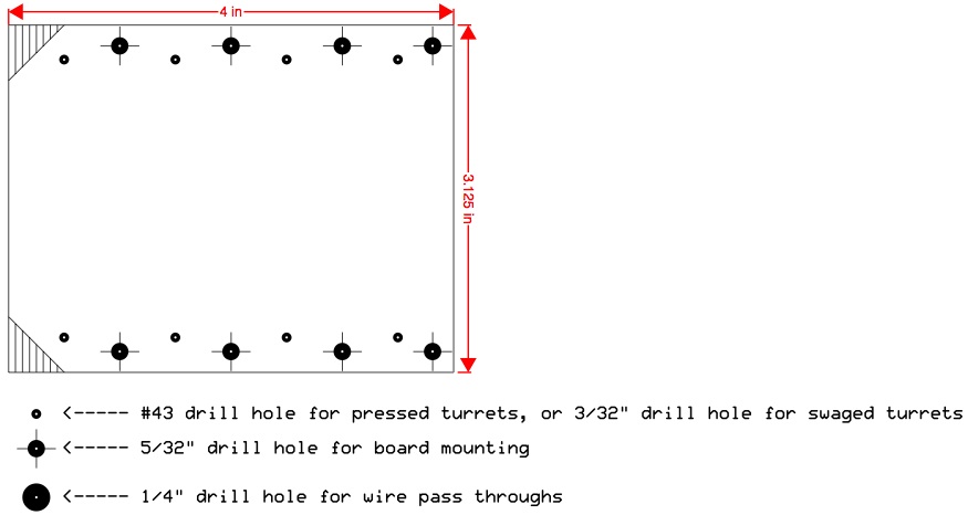
After the holes were drilled to their proper size (3/32″ for swaged turrets, 5/32″ for board mounting, and 1/4″ for wire pass throughs) it was time to swage the turrets into place.

Circuit Board - Swaging Turrets

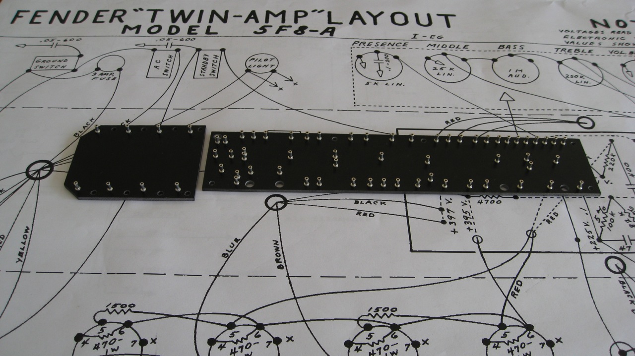
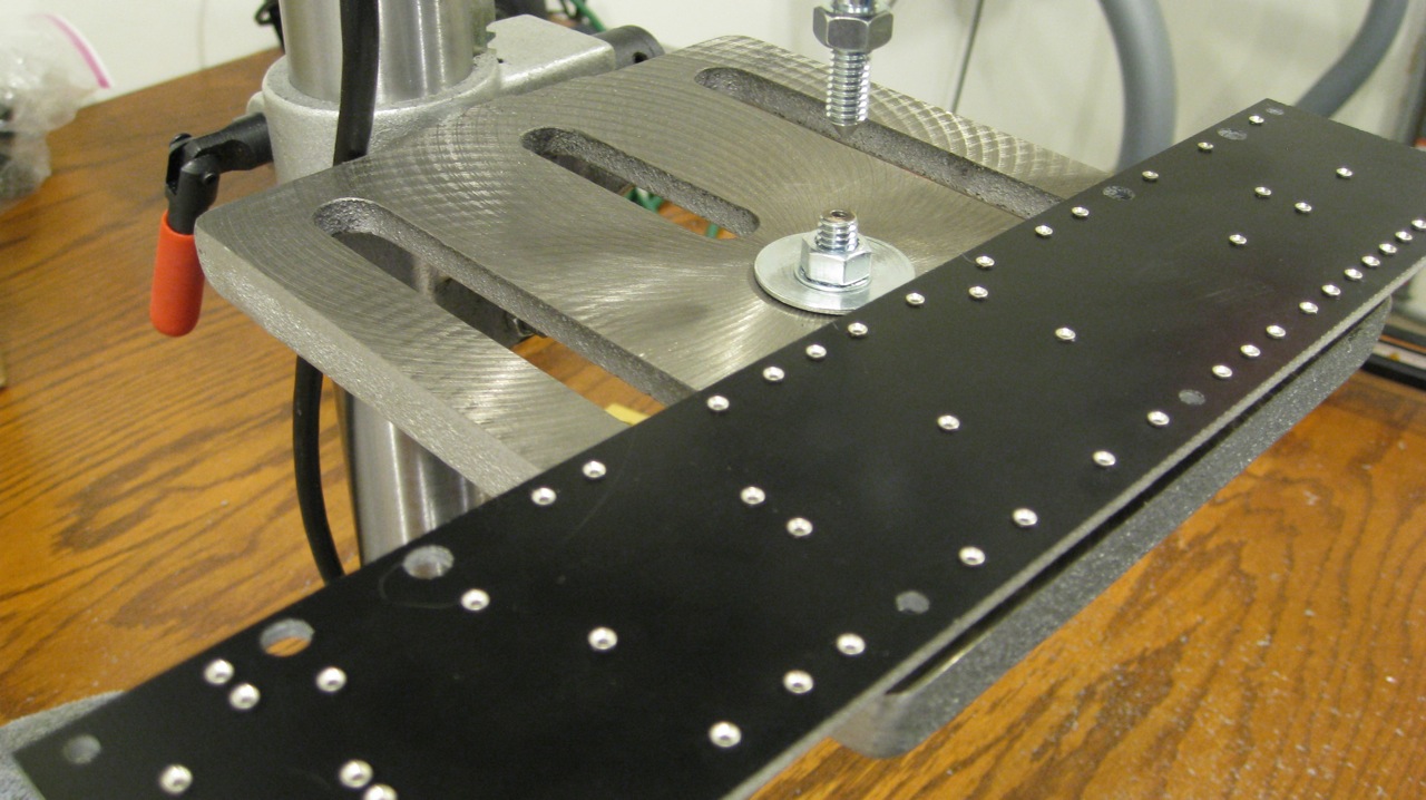
The completed circuit boards came out nicely:

Circuit Board - Turrets Installed

I welcome any comments, corrections, or thoughts on this subject.
Adjustable Bias Layout

I plan to modify the original Fender 5F8A circuit to include an adjustable bias. This modification would incorporate a linear potentiometer that is wired like a variable resistor (i.e. one leg of the potentiometer is left unconnected).

One such method is to replace the original 56 K Ohm resistor with a 50 K Ohm linear potentiometer and a 10 K Ohm resistor (Weber Method).

Another approach is to use a 50 K Ohm linear potentiometer along with the original 56 K Ohm resistor (Hoffman Amps Method). According to the Hoffman Amps technical library, the use of the original 56 K Ohm resistor ensures that “the bias voltage can never short out directly to ground when the bias potentiometer is turned to zero Ohms.”

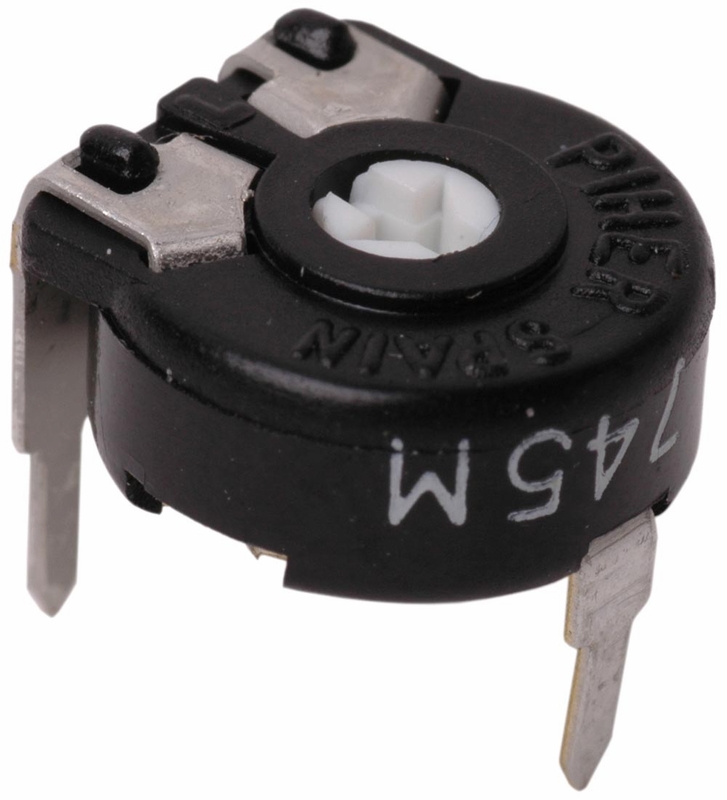
I obtained the following 50 K Ohm potentiometer from TubeDepot.com:

Bias Trim Potentiometer

The original circuit layout had to be redesigned to accommodate the shorter leads of metal film resistors (versus the longer leads of vintage carbon composition resistors). During the circuit board redesign I incorporated the adjustable bias modification as illustrated below.

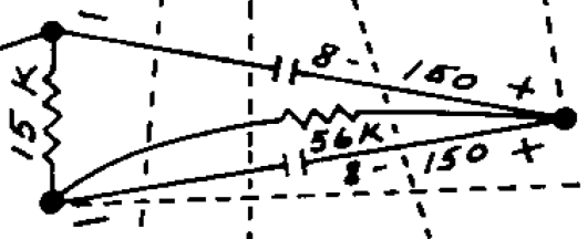
The original Fender 5F8A fixed bias circuit layout:
Original 5F8A Fixed Bias Layout

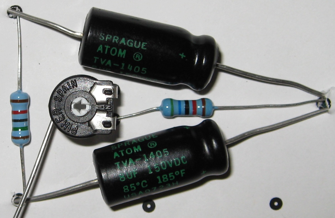
My redesigned adjustable bias circuit layout:
Adjustable Bias Modification Layout

In the end, I decided to use a 10 K Ohm resistor with the 50 K Ohm potentiometer… I figured that would provide enough adjustment, i.e. with the 50 K Ohm potentiometer set at halfway, the total resistance would equate to 35 K Ohms. Note that the above photo depicts a 56 K Ohm resistor, which was only used for layout purposes.

I welcome any comments, corrections, or thoughts on this subject.
New Circuit Board Layout

The original circuit layout had to be redesigned to accommodate the shorter leads of metal film resistors (versus the longer leads of vintage carbon composition resistors).

I attempted to maintain the original X-axis component spacing as much as possible, using the original 5F8A layout as a scaled reference. Some modifications were made, such as the use of turrets instead of eyelets and the addition of a linear potentiometer for an adjustable bias circuit.

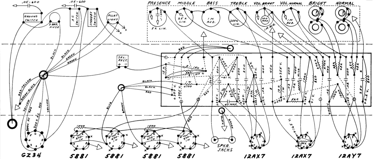
The original Fender 5F8A circuit board:

Original Fender 5F8A Circuit Board

My redesigned 5F8A circuit board:

Redesigned 5F8A Circuit Board

My redesigned 5F8A filter capacitor board:

Redesigned Filter Capacitor Board

I welcome any comments, corrections, or thoughts on this subject.
Welcome…

Welcome to the Fender Twin Tweed Project builder site.

The purpose of this website is to document my progress as I build a late 50’s Fender Twin Tweed (5F8A) guitar amplifier.

Also, I look forward to comments from other amplifier builders; in attempt to further my knowledge base throughout the process.

Hopefully, others will be able to utilize the information on this website to assist them with their projects.

Sincerely,

Todd

Fender 5F8A Circuit Layout