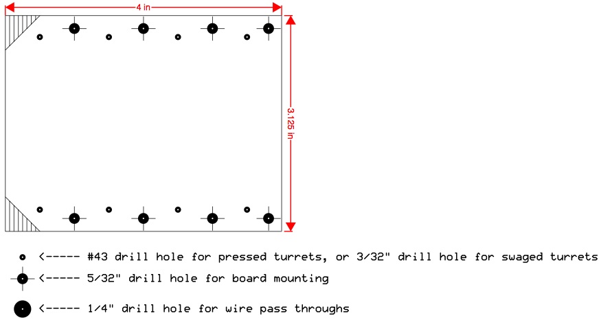
The original circuit layout had to be redesigned to accommodate the shorter leads of metal film resistors (versus the longer leads of vintage carbon composition resistors).
I attempted to maintain the original X-axis component spacing as much as possible, using the original 5F8A layout as a scaled reference. Some modifications were made, such as the use of turrets instead of eyelets and the addition of a linear potentiometer for an adjustable bias circuit.
The original Fender 5F8A circuit board:
My redesigned 5F8A circuit board:
My redesigned 5F8A filter capacitor board:
I welcome any comments, corrections, or thoughts on this subject.


