I chose 1/8″ G-10, a flameproof rated glass epoxy material, for my circuit boards. When purchasing the G-10, I requested the boards to be cut to length (12″ for main circuit board, 4″ for filter cap board) but the main circuit board still needed to be ripped from 3-1/8″ wide to its finish width of 2-1/2″ (for more info on why, see post: New Circuit Board Layout). To rip the G-10 board lengthwise, I used an orbital jig saw and a fence to ensure that my cut was straight. The finished cut was clean and straight, but the glass epoxy G-10 board made mincemeat of my blade.
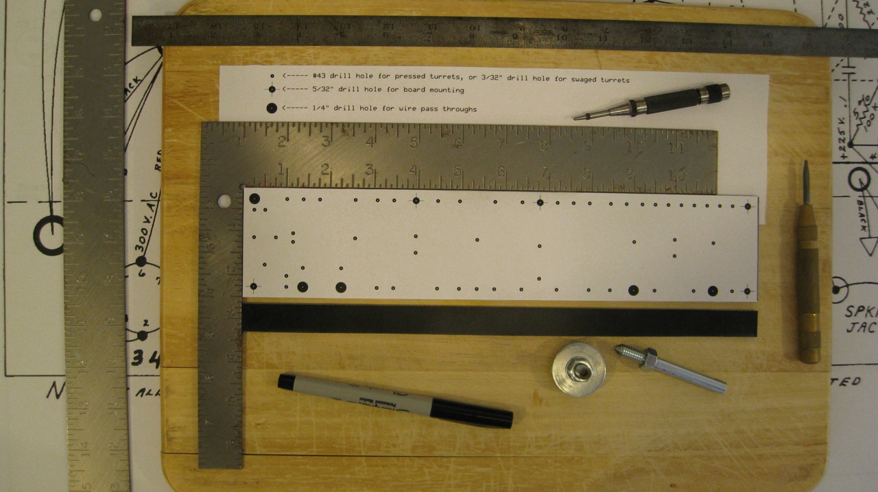
The next step was to transfer the turret and hole layout onto the G-10 board, using my redesigned circuit board layout. I used a center-punch to mark the hole locations.
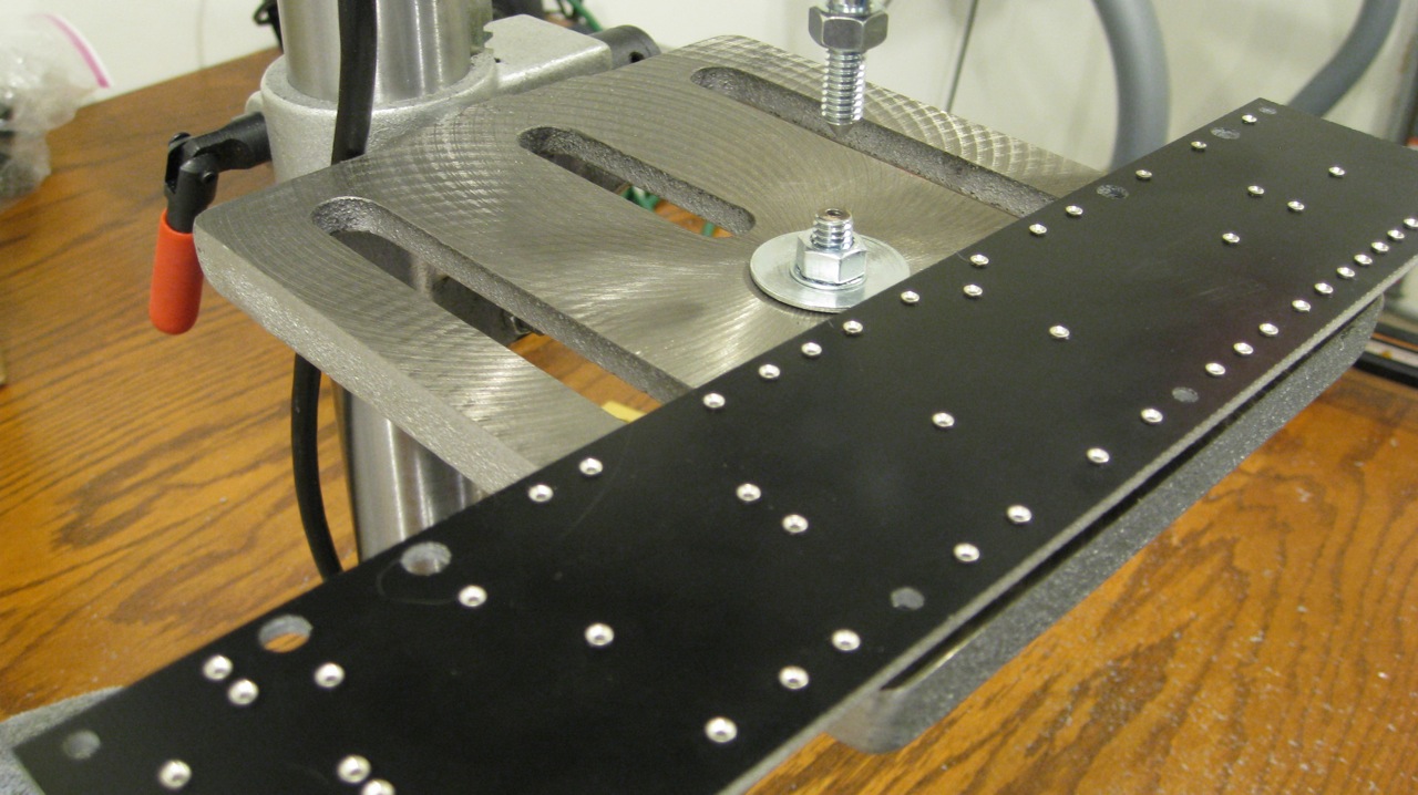
After using my friend’s drill-press for several other projects, I decided that it was prudent to purchase one of my own. For ease of storage and space considerations, I decided to get a 10 inch table drill-press. Within 30 minutes I had the drill-press assembled and properly adjusted. My first project using my new drill-press was to fabricate an anvil and swage out of two 5/16″ bolts. I followed the tutorial available on TubeDepot.com.
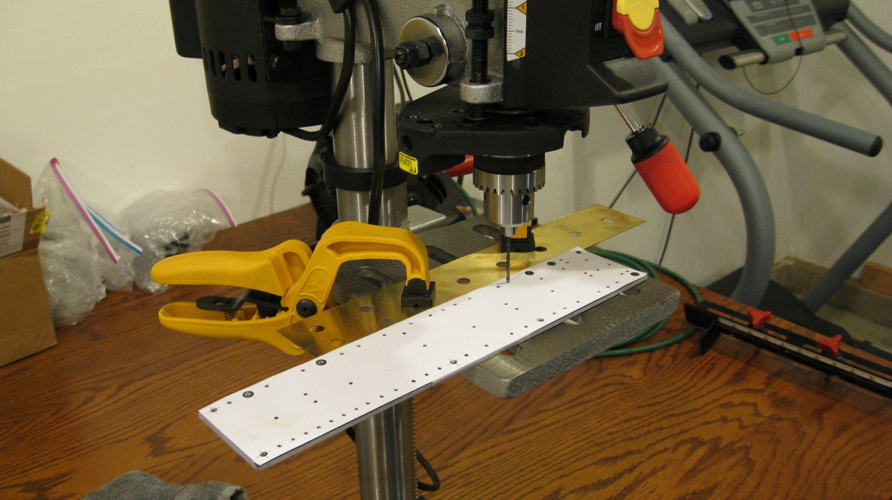
Next, it was time to drill all of the circuit board holes. I thought that it would be easier locate and align the drill if I didn’t remove the paper template; and because the paper template was securely attached to the G-10 with pieces of Scotch tape I decided to simply leave it attached during the drilling process.
After the holes were drilled to their proper size (3/32″ for swaged turrets, 5/32″ for board mounting, and 1/4″ for wire pass throughs) it was time to swage the turrets into place.
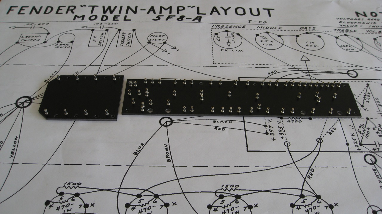
The completed circuit boards came out nicely:
I welcome any comments, corrections, or thoughts on this subject.


